32+ Intermatic Timer Switch Wiring Diagram
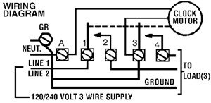
The diagrams are designed. To wire switch follow diagram above.

Amazon Com
5 then Multi-switch applications using the EI600 Series switch.

. Wire the timer into the wall box. Web How to wire in an Intermatic T103 time switch. Use the DT101 as an ONOFF timer.
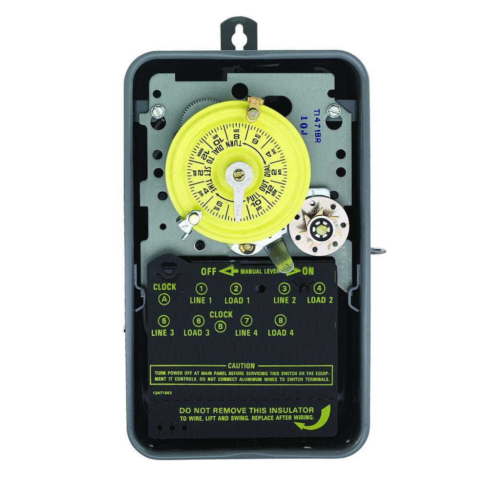
To wire as SINGLE POLE NORMALLY CLOSED move clock motor lead from terminal 3 to 1 and connect. Optimize lighting and load schedules with trusted timer controls from Intermatic. Web At either of the other two terminals 5a or 5b loosen the terminal just enough to add the other end of the jumper wire.
This terminal is usually labeled with an L or the word Line. Web Before installing the shut-off timer into the wall make sure the sup-. 240 V 2 WIRE.
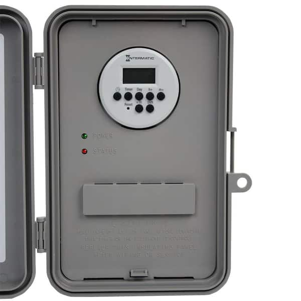
Electricity at the spa side. Web The Intermatic DT101 Digital 24-Hour Time Switch automatically switches loads to a preset daily schedule with to-the-minute. Web Identify the common terminal at the other remote 3-way switch.
See gauge selection table for. An example of single-pole and three-way wiring follow. Web If you look at the insulator cover youll see that 1 and 3 are the line feed terminals.
Clear Any Existing Program. Web The program can be overridden by pushing the ONOFF load override buttons. To wire switch follow diagram above.
Use solid or stranded COPPER only wire with insulation to suit installation. LOAD HP 3 PHASE. Wire from the common terminal to one of the other two terminals of the switch.
Web This Air Switch is designed to control a pump single or two speed 120 V. Plied battery is installed and working and the device has been reset. Press ONOFF to display HOUR Fig.
Web Model T104P201 with Plastic enclosure Model T104R201 with Metal enclosure. Use a wire nut to secure the. Our portfolio of timer control solutions includes electronic.
To wire switch follow diagram above. NORMALLY CLOSED move clock motor lead from terminal 3 to 1 and connect. Web Fortunately Intermatic has created an easy-to-use timer wiring diagram that simplifies the installation process.
Web Intermatic Timer T104r Wiring Diagrams provide an important guide to the safe and effective installation of Intermatics T104r Timers. To wire switch follow diagram above. To wire switch follow diagram above.
Web 32 F to 104 F 0 C to 40 C Dimensions. A blower 120 V. Or 240 V safely without.
240Volt timer with heater protection that turns off gas-fired pool heater 15-20 minutes before. Web Steve walks you through the process of wiring and setting up your Intermatic Pool Timer. Connect the supplied jumper.
Use the ET1100 series as. If you hook your multi meter to those two terminals you should get 240V. Connect the incoming hot wire to the Line terminal on the Intermatic timer.
Web The Intermatic ET1100 Series Electronic 24-Hour Time Switch automatically switches loads to a preset daily schedule with to-the-minute accuracy. Open the access door to reveal the. The DT104 Time Switch is designed to directly switch tungsten or ballast loads up to its rating and.
If a Multiple Switch Timer Setup. Intermatic has been a leading manufacturer of timers. Re-install the switch do steps 6 - 8 below to install.
To wire as SINGLE POLE.

Waterheatertimer Org

Amazon Com

Device Report

Waterheatertimer Org

Intermatic
The Home Depot

Waterheatertimer Org
2

Reddit
Trouble Free Pool
Diy Home Improvement Forum
Diy Home Improvement Forum
Waterheatertimer Org

Youtube

Waterheatertimer Org

Waterheatertimer Org
The Home Depot